
GENERAL CASE OF COMBINED STRESSES
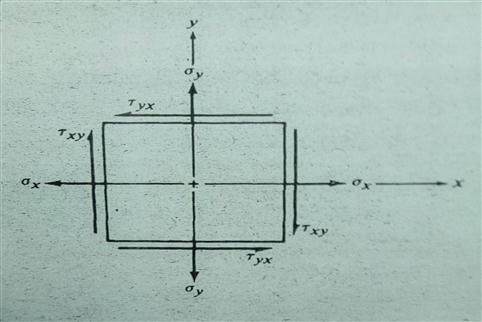
To visualize the general case of combined stresses, it is helpful to consider a small element of the load-carrying member on which combined normal and shear stresses act. For this discussion, we will consider a two-dimensional stress condition, as illustrated in Figure 4-3.
The normal stress σx and σy, could be due to a direct tensile force or to bending. If the normal stresses were compressive (negative), the vectors would be pointing in the opposite sense, into the stress element.
The shear stress could be due to direct shear, torsional shear, or vertical shear stress. The double-subscript notation helps to orient the direction of shear stresses. For example, τxy indicates the shear stress acting on the element face that is perpendicular to the x-axis and parallel to the y-axis.
A positive shear stress is one that tends to rotate the stress element clockwise.
In Figure 4-3, τxy is npositive, and τyx is negative. Their magnitudes must be equal to maintain the element in equilibrium.
It is necessary to determine the magnitudes and the signs of each of these stresses in order to show them properly on the stress element. Example Problem 4-1, which follows the definition of principal stresses, illustrates the process.
FIGURE 4-3
General two-dimensional
stress element
With the stress element defined, the objectives of the remaining analysis are to determine the maximum normal stress, the maximum shear stress, and the planes on which these stresses occur. The governing formulas follow. (See reference 1 for the derivations.)